BSE_Template_Portfolio
This is my Gesture Controlled Robot Page!
Project maintained by LoreleiXia Hosted on GitHub Pages — Theme by mattgraham
Gesture-Controlled Robot Car!!
In many science-fiction TV shows and movie series, directors produce scenes where objects can be moved without manual relocation. Imitating this remote-controlled ability, I developed a robot-car that can move in different orientations according to different hand gestures!
| Engineer | School | Area of Interest | Grade |
|---|---|---|---|
| Lorelei X. | IHS | Biomedical Engineering | Junior |

Final Presentation
Overall, my experience with the development of the gesture-controlled robot car has been exceptionalyl enthralling. Throughout the duration of my project development, I trouble-shooted series of code, modified the vehicle’s physical characteristics to increase simpplicity and efficiency, and practiced efficient documentation. Branching from the base project, I was also able to use my knowledge in software and mechanical engineering to add additional modifications. I’m excited to use the variety of workflow, engineering, and experimentation skills in future projects!
Final Milestone
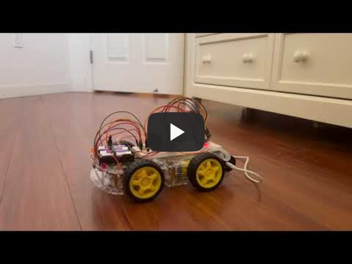
For my final milestone, I added a small modifcation of 4 LED lights. These LED lights are used to replicate the tailights of a regular car. I designed it so when the car is stopping, the red light would turn on. When the car is in reverse, the white lights would turn on. When the car is turning, the orange light would turn on. In adding these additioal modifications, I experienced difficulties in the organization of the vehicles parts, as the addition of the four lights and their respective wires increased the complexity of the vehicle system. While this is the preliminary end to my project design, I hope to increase the robot-car’s realism. With the addition of safety systems - systems where the car would stop before crashing, sound and blinking systems (signaling, beeping) - I could mimic a real life car!
Second Milestone
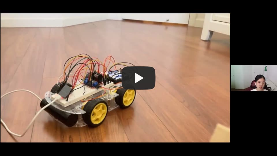
My second milestone was to configure a setup where accelerometer values would be read and used to move the car accordingly. I began with testing out the accelerometer output values and understanding the orientation values (x,y,z). I then plugged the accelerometer into a secondary ESP, which would transmit the values from the accelerometer, which was theoretically placed on the user’s hand, to the ESP attached to the vehicle. With this, I coded different x,y, and z thresholds for right, left, front, and backward directions. If the accelerometer values crossed these thresholds, the car would alter it’s orientation to the respective direction. Eventually, after securing the secondary ESP to the vehicle and adjusting the accelerometer parameters, I was able to successfully move the car according to different gestures! For my next milestone, I hope to achieve a LED light indicator system, which would light up according to the direction that the vehicle is going, similarly to a regular car!
First Milestone
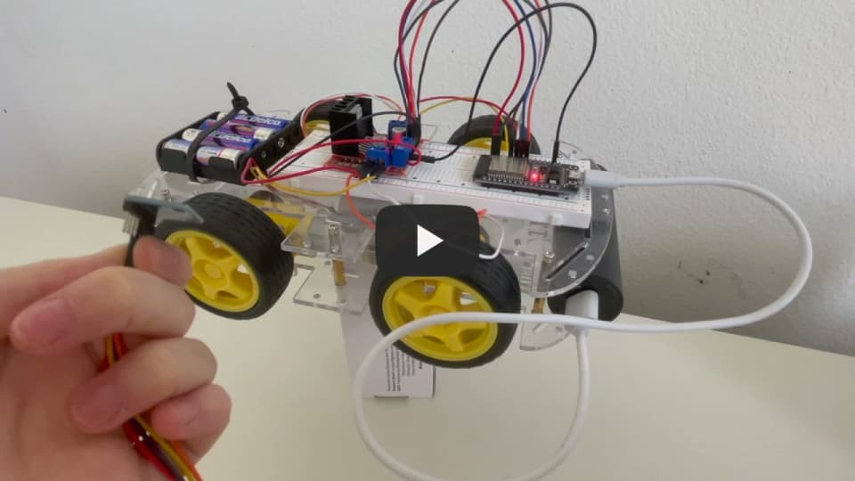
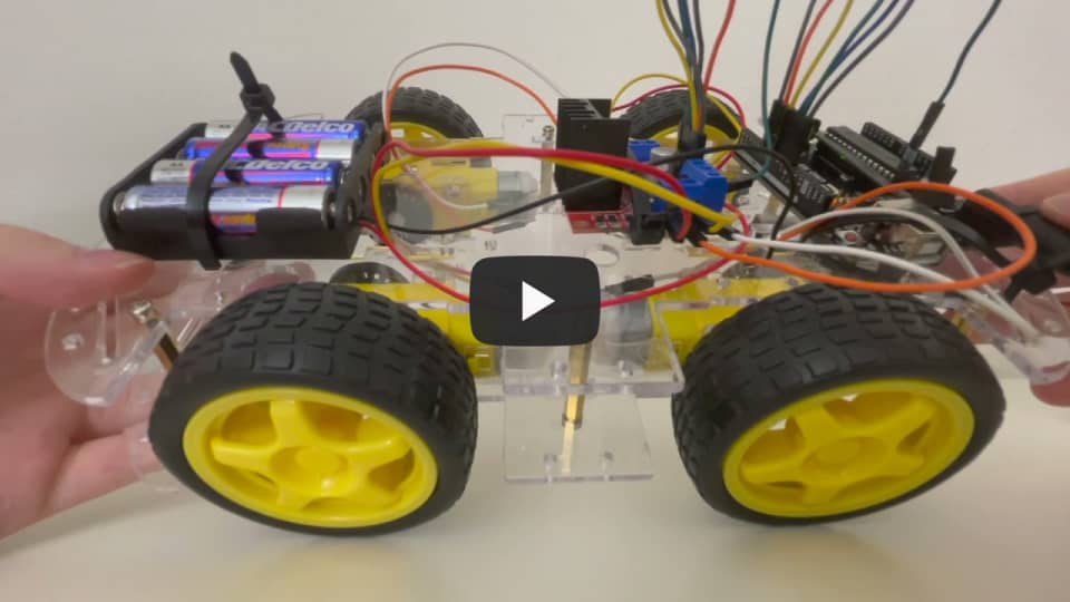
For my first milestone, I studied the function of motors and motor drivers, and how I could utilize them in my gesture-controlled robot car. I started by constructing the foundation of my robot car, securing the motors, wheels, motor-drivers to the car chassis. To test the efficiency of two of the motors, I used a set of jumper wire to manually turn on each motor, watching the wheels turn in different directions. As a result from its success, I added two more motors to the base, completing the foundation of my gesture-controlled car. To avoid having to power the car manually, I compiled a simple code that could move all 4 tires simultaneously at a fixed speed and direction. However, the vehicle in its current state must be manually run by each code execution. For my next milestone, I hope to use the accelerometer to begin developing a more automatic driving system.
Photos


Circuit Diagram
Robot Car:

Glove:

Code
Sender Code:
/*
  Rui Santos
  Complete project details at https://RandomNerdTutorials.com/esp-now-esp32-arduino-ide/

  Permission is hereby granted, free of charge, to any person obtaining a copy
  of this software and associated documentation files.

  The above copyright notice and this permission notice shall be included in all
  copies or substantial portions of the Software.
*/

#include <esp_now.h>
#include <WiFi.h>

#include <Adafruit_MPU6050.h>
#include <Adafruit_Sensor.h>
#include <Wire.h>

Adafruit_MPU6050 mpu;

int gyro_x, gyro_y, gyro_z;
long acc_x, acc_y, acc_z, acc_total_vector;
int temperature;
long gyro_x_cal, gyro_y_cal, gyro_z_cal;
long loop_timer;
int lcd_loop_counter;
float angle_pitch, angle_roll;
int angle_pitch_buffer, angle_roll_buffer;
boolean set_gyro_angles;
float angle_roll_acc, angle_pitch_acc;
float angle_pitch_output, angle_roll_output;


/////////////////////////////////////////////////////////////////////////


// REPLACE WITH YOUR RECEIVER MAC Address
uint8_t broadcastAddress[] = {0xE0, 0xE2, 0xE6, 0xC6, 0x35, 0x38};

// Structure example to send data
// Must match the receiver structure
typedef struct struct_message {
  float b;
  float c;
  bool e;
} struct_message;

// Create a struct_message called myData
struct_message myData;

// callback when data is sent
void OnDataSent(const uint8_t *mac_addr, esp_now_send_status_t status) {
  Serial.print("\r\nLast Packet Send Status:\t");
  Serial.println(status == ESP_NOW_SEND_SUCCESS ? "Delivery Success" : "Delivery Fail");
}

void setup() {
  // Init Serial Monitor
  Serial.begin(115200);


    // Try to initialize!
  if (!mpu.begin()) {
    Serial.println("Failed to find MPU6050 chip");
    while (1) {
      delay(10);
    }
  }
  Serial.println("MPU6050 Found!");

  mpu.setAccelerometerRange(MPU6050_RANGE_8_G);

  mpu.setGyroRange(MPU6050_RANGE_500_DEG);

  mpu.setFilterBandwidth(MPU6050_BAND_5_HZ);


//////////////////////////////////////////////////////////////


  // Set device as a Wi-Fi Station
  WiFi.mode(WIFI_STA);

  // Init ESP-NOW
  if (esp_now_init() != ESP_OK) {
    Serial.println("Error initializing ESP-NOW");
    return;
  }

  // Once ESPNow is successfully Init, we will register for Send CB to
  // get the status of Trasnmitted packet
  esp_now_register_send_cb(OnDataSent);

  // Register peer
  esp_now_peer_info_t peerInfo;
  memcpy(peerInfo.peer_addr, broadcastAddress, 6);
  peerInfo.channel = 0;
  peerInfo.encrypt = false;

  // Add peer
  if (esp_now_add_peer(&peerInfo) != ESP_OK){
    Serial.println("Failed to add peer");
    return;
  }
}

void loop() {
  // Set values to send
  sensors_event_t a, g, temp;
  mpu.getEvent(&a, &g, &temp);

  acc_total_vector = sqrt((a.acceleration.x*a.acceleration.x)+(a.acceleration.y*a.acceleration.y)+(a.acceleration.z*a.acceleration.z));  //Calculate the total accelerometer vector
  //57.296 = 1 / (3.142 / 180) The Arduino asin function is in radians
  angle_pitch_acc = asin((float)a.acceleration.y/acc_total_vector)* 57.296;       //Calculate the pitch angle
  angle_roll_acc = asin((float)a.acceleration.x/acc_total_vector)* -57.296;       //Calculate the roll angle

  angle_pitch_acc -= 0;                                              //Accelerometer calibration value for pitch
  angle_roll_acc -= 0;

  myData.b = angle_pitch_acc;
  myData.c = angle_roll_acc;
  myData.e = true;

  Serial.print("acc_pitch: ");
  Serial.print(myData.b);
  Serial.print("    acc_roll: ");
  Serial.println(myData.c);

  // Send message via ESP-NOW
  esp_err_t result = esp_now_send(broadcastAddress, (uint8_t *) &myData, sizeof(myData));

  if (result == ESP_OK) {
    Serial.println("Sent with success");

  }
  else {
    Serial.println("Error sending the data");
  }
  delay(1000);
}
Reciever Code:
/*
  Rui Santos
  Complete project details at https://RandomNerdTutorials.com/esp-now-esp32-arduino-ide/

  Permission is hereby granted, free of charge, to any person obtaining a copy
  of this software and associated documentation files.

  The above copyright notice and this permission notice shall be included in all
  copies or substantial portions of the Software.
*/

#include <esp_now.h>
#include <WiFi.h>
#include<analogWrite.h>

// Structure example to receive data
// Must match the sender structure
typedef struct struct_message {

    float b;
    float c;
    bool e;
} struct_message;

int len;

String command;

  const int in1 = 23;

  const int in2 = 5;

  const int in3 = 18;

  const int in4 = 19;

  const int enA = 22;

  const int enB = 21;

// Create a struct_message called myData
struct_message myData;

// callback function that will be executed when data is received
void OnDataRecv(const uint8_t * mac, const uint8_t *incomingData, int len) {
  memcpy(&myData, incomingData, sizeof(myData));

  /*
  Serial.print("Bytes received: ");
  Serial.println(len);
  Serial.print("Char: ");
  Serial.println(myData.a);
  Serial.print("Int: ");
  Serial.println(myData.b);
  Serial.print("Float: ");
  Serial.println(myData.c);
  Serial.print("String: ");
  Serial.println(myData.d);
  Serial.print("Bool: ");
  Serial.println(myData.e);
  Serial.println(); */
}

void setup() {
  // Initialize Serial Monitor
  pinMode(in1, OUTPUT);
  pinMode(in2, OUTPUT);
  pinMode(in3, OUTPUT);
  pinMode(in4, OUTPUT);
  pinMode(enA, OUTPUT);
  pinMode(enB, OUTPUT);
  Serial.begin(115200);

  // Set device as a Wi-Fi Station
  WiFi.mode(WIFI_STA);

  // Init ESP-NOW
  if (esp_now_init() != ESP_OK) {
    Serial.println("Error initializing ESP-NOW");
    return;
  }

  // Once ESPNow is successfully Init, we will register for recv CB to
  // get recv packer info
  //  esp_now_register_recv_cb(OnDataRecv);
}

void loop() {
  esp_now_register_recv_cb(OnDataRecv);

  if(myData.e){
        Serial.print("Bytes received: ");
        Serial.println(len);
        Serial.print("Pitch: ");
        Serial.println(myData.b);
        Serial.print("Roll: ");
        Serial.println(myData.c);
        Serial.print("Bool: ");
        Serial.println(myData.e);
        Serial.println();
        myData.e = false;
  }

  if(myData.b <= -50.00 && myData.c >= -2){ // forwards
        digitalWrite(in1, HIGH);
        digitalWrite(in2, LOW);
        digitalWrite(in3, HIGH);
        digitalWrite(in4, LOW);
        analogWrite(enA, 245);
        analogWrite(enB, 245);
        Serial.println("Forwards");

  }

  if(myData.c >= 40.00){ // right
        digitalWrite(in1, HIGH);
        digitalWrite(in2, LOW);
        digitalWrite(in3, LOW);
        digitalWrite(in4, LOW);
        Serial.println("Right");
        analogWrite(enA, 245);
        analogWrite(enB, 245);

  }

  if(myData.c <= -40.00){ // left
        digitalWrite(in1, LOW);
        digitalWrite(in2, LOW);
        digitalWrite(in3, HIGH);
        digitalWrite(in4, LOW);
        Serial.println("Left");
        analogWrite(enA, 245);
        analogWrite(enB, 245);

  }

  if(myData.b >= 40){ // backwards
        digitalWrite(in1, LOW);
        digitalWrite(in2, HIGH);
        digitalWrite(in3, LOW);
        digitalWrite(in4, HIGH);
        analogWrite(enA, 245);
        analogWrite(enB, 245);
        Serial.println("Backwards");

  }


}